
How GPS grading system works for road construction projects
How GPS grading works on road projects, where its limits genuinely are, and how teams on major motorways manage mixed fleets — Trimble, Topcon, Leica and more — without the portal chaos.
Request a demo
Not whether GPS grading works — it does — but how to get the most out of it, understand where its limits genuinely are, and manage a mixed GPS fleet without the data chaos that tends to follow.
Most GPS grading failures on road projects are not GPS failures. The technology works. Operators run blade guidance reliably on subgrade and base course day after day. The problem appears later — when a design revision comes through, a surveyor has to push the update through four different manufacturer portals, and a dozer somewhere on site keeps cutting from yesterday's model for an hour before anyone catches it.
That is the gap this article is about. Not whether GPS grading works — it does, and for the vast majority of earthworks it has largely replaced grade staking — but how to get the most out of it, understand where its limits genuinely are, and manage a mixed GPS fleet without the data chaos that tends to follow.
What is a GPS grading system?
A GPS grading system puts the design model inside the cab. A GNSS receiver mounted on the machine — on the blade, the bucket, or a mast — establishes its precise 3D position in real time. That position is compared continuously to a digital terrain model: the finished road surface as the designer intended it. The cab display shows the operator exactly how much to cut or fill at every point, updated many times per second.
Before GPS, operators relied on grade stakes — wooden markers every 15–20 metres showing cut or fill depths. Surveyors spent days staking sites. Stakes got knocked over. Accuracy depended heavily on operator experience and feel.GPS changed the equation. The machine knows where it is to centimetre accuracy. Load the design model once. Get continuous real-time guidance across the entire work area. Less experienced operators can achieve results that previously required years of skill to develop.
The GNSS receiver communicates with multiple satellite constellations — GPS, GLONASS, Galileo, BeiDou — and combines that signal with corrections from a local RTK base station or a network correction service.
In good conditions on a road site, vertical accuracies of 10–20 mm are achievable. Inertial measurement units (IMUs) maintain guidance when satellite signals are briefly blocked by terrain or structures.
2D vs 3D machine control: What the difference means on site
Not all GPS grading systems are the same. The most important distinction for road construction is 2D versus 3D.
A 2D system controls one slope at a time — typically using a laser or sonic tracker for vertical reference. It works for consistent, simple grades: a uniform cross-fall across a flat section, or a long straight cut at a known slope. Simple to set up, lower cost, and adequate for straightforward work.
A 3D GPS grading system loads the complete design surface and positions the machine against it in all three dimensions.
Variable super-elevation, transitions, intersections, changing cut depths along the alignment — all handled automatically by the model. The operator does not need to recalculate or wait for a surveyor to reset stakes as the geometry changes. The system always knows what the design calls for at the current machine position.
For any road project with significant geometric complexity — which is most of them — 3D is the practical standard. The productivity difference on complex alignment sections is substantial.
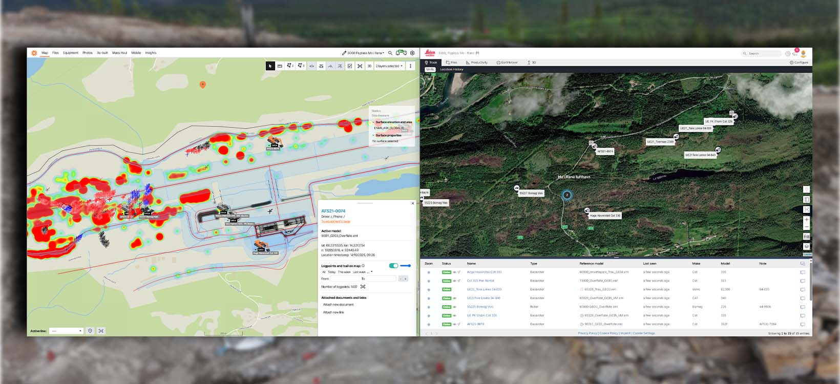
3D machine control also makes as-built data collection possible as a by-product of normal work. Because the system logs the machine's 3D position continuously, it creates a record of what was actually graded. That record can be compared to the design model automatically, without a separate survey exercise — which is where a lot of the quality documentation value comes from. See how Infrakit connects as-built data to one map →
GPS grading system for dozer: where it adds the most value
The dozer is typically the first machine on a road corridor — stripping topsoil, moving bulk material, establishing rough subgrade. A GPS grading system for dozer work mounts GNSS receivers on the blade, combined with slope sensors, to keep the blade in continuous relationship to the 3D design surface.
The gains on bulk earthworks are mostly about material efficiency. A GPS-guided dozer makes fewer passes to reach target grade. Over-excavation — cutting deeper than the design requires and then importing fill to compensate — drops significantly. On large embankment and cut sections, the difference in imported material, fuel, and machine hours adds up quickly.
There is also a practical safety benefit that is easy to underestimate. Operators in GPS-guided machines need fewer ground personnel nearby for grade checks. Fewer people on foot around moving equipment is a meaningful reduction in exposure.
The dozer sets up the work for the motor grader, which finishes the surface to tighter tolerances. This sequence — dozer for bulk earthworks, grader for finish grade — is where most of the production efficiency on a GPS-guided road project is realised. The dozer does not need to nail the final surface. It needs to get close, efficiently. GPS handles that task well.
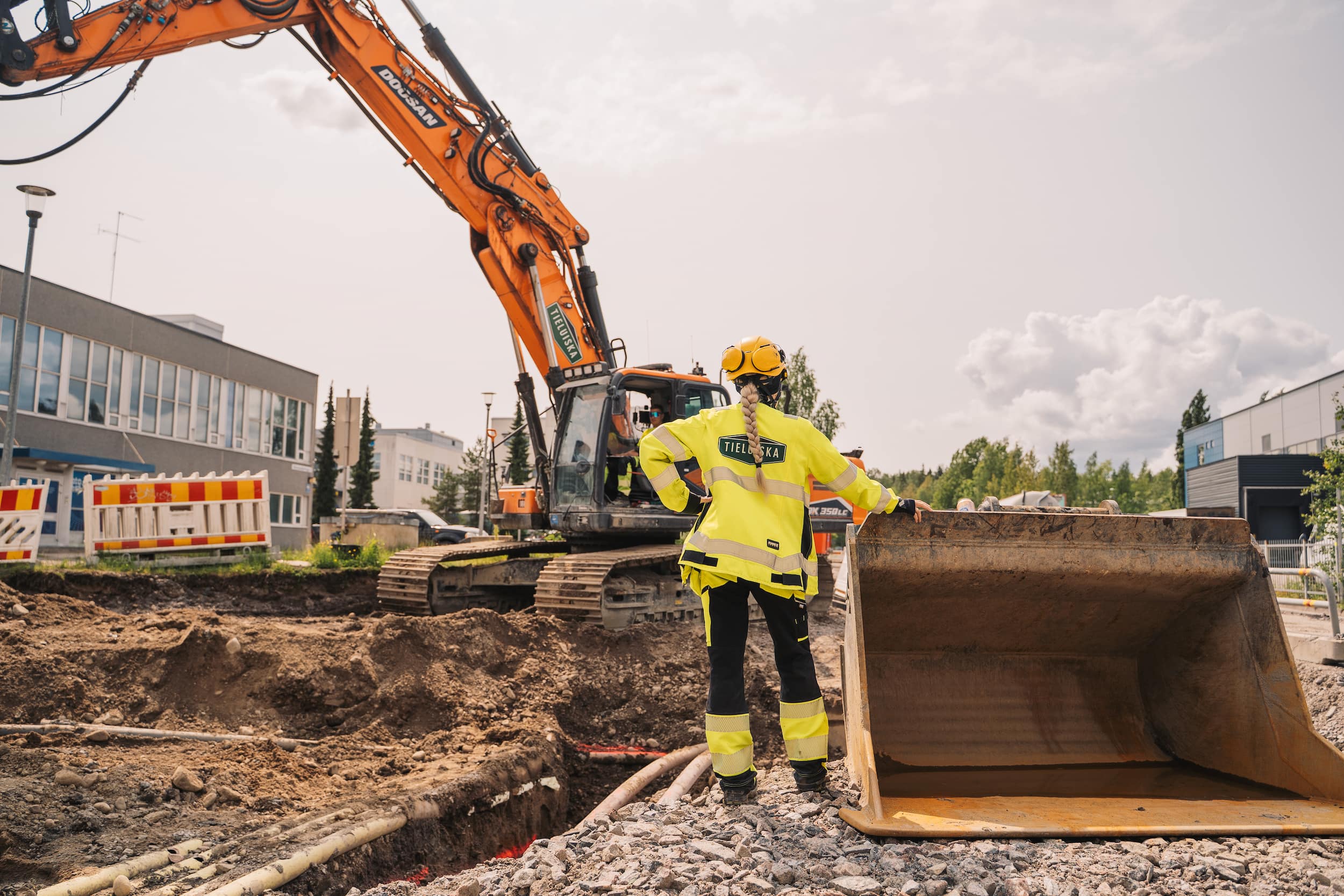
The same principle applies to excavator guidance. On one well-documented sitework project, a grading task that would typically take a full week was completed in a day and a half after switching from stringlines and manual grade checks to in-cab GPS guidance. The time saving was not just from faster digging — workers who had previously been tied up pulling stringlines and verifying elevations could be reassigned to other productive tasks around the site. That labour reallocation is often more valuable than the guidance accuracy itself.
The machine's as-built log also feeds mass haul calculations and payment records. Because the data is generated automatically during normal operation, it is available immediately — not after a surveyor has completed a separate measurement exercise.



GPS vs manual grading: the honest answer
This is the question that comes up most often on sites adopting machine control. The honest answer is that GPS grading is not a universal replacement for manual methods — and teams that treat it as one run into trouble.
The practical consensus is roughly this: GPS handles rough grading, subgrade, and base course work reliably and efficiently. For final surfaces — wearing course, concrete paving, curb setting — most experienced teams still reach for total stations, stringlines, or millimetre laser systems.
GPS satellites are constantly moving. The geometry of which satellites are visible — and where they sit in the sky — directly affects vertical accuracy. A reading taken at 9am and another at 3pm on the same point can differ by 15 mm or more, not because anything on the ground changed, but because the receiver is working from a completely different set of satellite positions. For subgrade that is within spec. For a wearing course it is not.
There is a useful way to think about the transition from manual to GPS-guided work. When experienced contractors first test GPS guidance alongside their traditional methods — running GPS for part of a stretch while keeping stringlines as a check — the comparison tends to go one of two ways.
Either the results match closely and confidence builds quickly, or there is a discrepancy that reveals a calibration issue worth catching. Either outcome is useful. What does not work is assuming the system is accurate without ever verifying it against known ground truth.
There is another dimension the spec sheets do not cover: the material itself.
Getting within a few millimetres is genuinely difficult when grading 25 mm crushed rock, regardless of what the receiver shows. GPS accuracy is bounded above by physical reality — the blade can only be as precise as the surface it is working allows.
With experience, teams typically reach this working model: use GPS confidently for everything up to base course, verify the first section of any new layer against a total station or known elevation, and reserve manual methods for the final surface elements where the tolerance genuinely demands them. The goal is not to replace all manual methods — it is to stop using them where they add no value.
Where GPS for road construction reliably delivers — and where it doesn't
Use GPS confidently for:
- >Rough grading and bulk earthworks — dozer and excavator work establishing subgrade
- >Subbase and base course layers — tolerances of ±20–30 mm are routinely achievable
- >Large open sections with consistent geometry and good satellite visibility
- >Cut and fill slopes where GPS speed advantage clearly outweighs any precision gap
- >Drainage channels and ditches where exact surface finish matters less than correct depth and fall
Supplement with total station or laser for:
- >Wearing course and final asphalt surfaces — ±5–10 mm tolerances where GPS vertical variability becomes marginal
- >Concrete paving and curb setting — most experienced teams still use stringline or TS here
- >Complex intersections and tight geometry changes where design model accuracy and field conditions need manual verification
- >Areas with poor satellite visibility — near buildings, under bridges, in steep-sided cuttings
- >Any element where the project specification requires TS verification regardless — know your contract requirements
A practical rule of thumb: civil tolerances for earthwork are typically specified at less than 30 mm deviation. When readings start drifting beyond 15 mm, it is worth stopping to verify the system against a known control point before continuing. That discipline alone prevents most GPS-related quality issues on road projects.
Calibration: the factor that determines real-world accuracy
GPS grading system marketing leads with satellite counts and update rates. What gets less attention — but matters just as much on site — is machine maintenance and regular calibration.
The GNSS receiver can be performing perfectly while worn blade edges, loose sensor mounts, or unchecked bushing wear introduce errors that dwarf the GPS precision figure. A machine that was calibrated at project start and never rechecked is not reliably working to its rated accuracy six weeks later. This is one of the most common sources of unexplained grade deviations on GPS-equipped projects — and one of the least glamorous to address.
On well-run projects, calibration is a scheduled, documented activity — not a one-time setup task. The standard process: the machine measures a known control point, the result is compared to the surveyed coordinate, and if the difference exceeds the project tolerance the system is adjusted before work continues.
What makes calibration work in practice is tracking results over time. A single calibration check tells you where the machine is today. A history of calibration checks tells you whether accuracy is drifting — and flags when something changed, such as a replaced sensor, repaired bucket pin, or worn cutting edge. That history also provides documentation if a quality question arises later about a specific stretch of road.
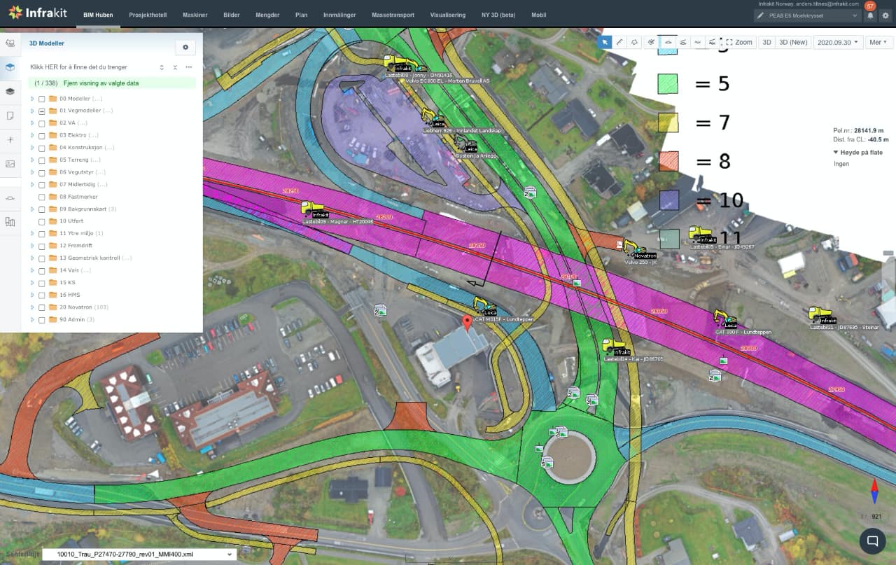
On PEAB's E6 Moelvkrysset road project in Norway, the team implemented weekly calibration checks for all GPS-guided machines on site. Each machine measured a known point, results were stored with timestamps, and an automatic alert fired if any reading fell outside the accuracy requirement. When a quality question came up about any section of road, the calibration history for the machine that worked it was immediately retrievable — giving the project clear documentation and protecting against disputes.
This kind of systematic calibration tracking is one of the clearest differences between projects that consistently hit their grade tolerances and those that struggle with unexplained deviations.
Managing GPS grading systems across a mixed fleet
A GPS grading system on a single machine delivers value at the machine level. The larger challenge on major road construction projects is managing a mixed fleet — and this is where many projects that should be running smoothly end up creating unnecessary work for their survey teams.
Here is how it typically unfolds. A design revision comes through — the alignment shifted to avoid a utility conflict discovered during excavation. The surveyor needs to push the updated model to the machines.
The project has Trimble-equipped excavators, a Leica-equipped grader from a subcontractor, Topcon on the rented dozers, and Novatron on the pipelaying kit. That means four manufacturer portals. Four uploads. Four different file format requirements. Forty-five minutes to push the update. Then another hour confirming which machines actually received it. One excavator timed out. The subcontractor's grader is not syncing. Another design change comes through tomorrow.
This is not a technology problem — every one of those GPS grading systems works well on its own. It is a data management problem. The survey team — whose expertise should be on quality control and design verification — spends their day as a data porter instead. On projects running five or more machine control platforms, that cost runs to several hours every week. That time is recoverable, but only if the data management layer changes.
One platform for every GPS grading system brand
One upload distributes to the entire fleet. As-built data flows back automatically, already standardised. Machine calibration logs are recorded and alerts flag accuracy drift automatically.
How teams on major road projects connect it all
The teams running large road projects with mixed GPS fleets have converged on a consistent answer: one platform connecting all machine control brands, sitting above the individual manufacturer systems.
The answer the industry has converged on is a single platform that sits above all the individual manufacturer systems — connecting every machine control brand through one interface. Infrakit is the construction data platform built specifically for this: it integrates with all major GPS machine control manufacturers, so models and as-built data flow through one place regardless of what equipment is on site.
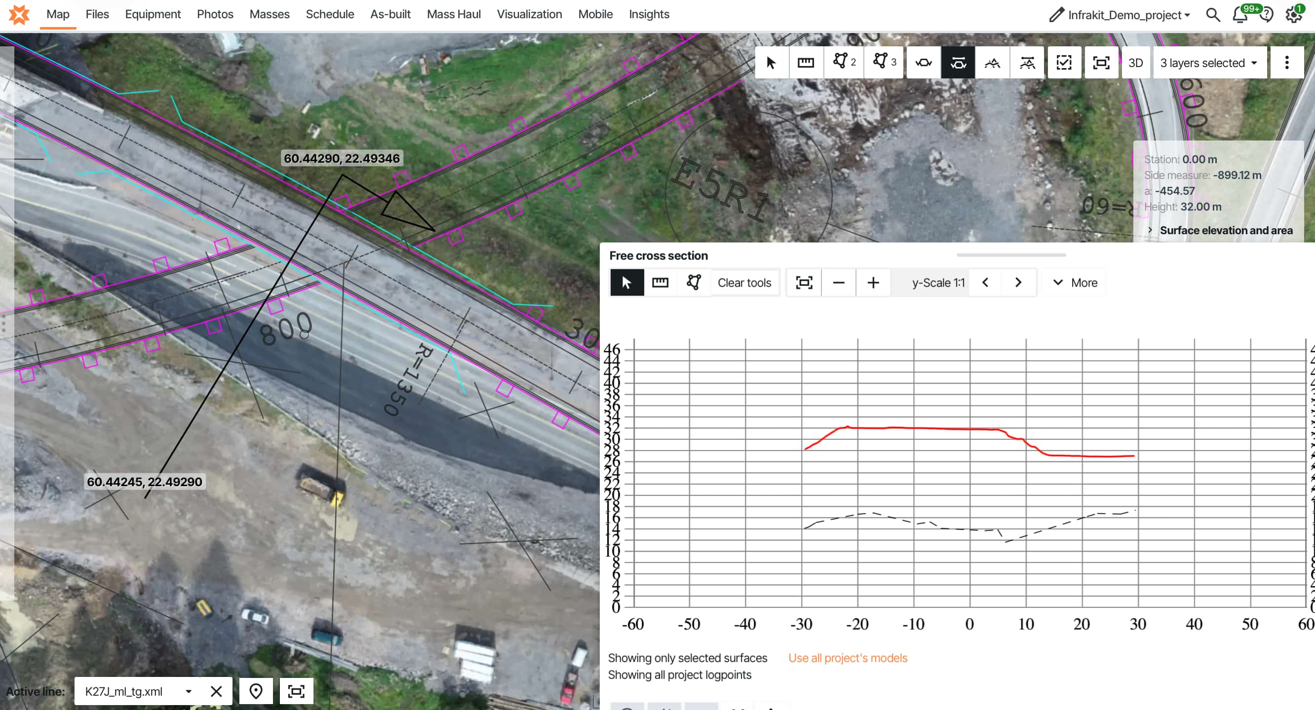
The integration works through manufacturer APIs. A design model is uploaded once to Infrakit, which automatically converts it to each manufacturer's required format and pushes it to their portal — Trimble WorksManager, Topcon Sitelink, Leica ConX, Novatron Xsite. One upload. Automatic distribution to the entire fleet. A single dashboard showing which model every machine has loaded and whether it is current.
As-built data flows back the same way — pulled from each manufacturer cloud, standardised, and displayed on one project map in real time regardless of which equipment generated it.
Operators keep using their familiar in-cab displays — Trimble Earthworks, Topcon 3D-MC, Leica iCON. Nothing changes at the machine level. The difference is entirely in how models reach the machines and how as-built data flows back to the office.
"Before, we used several programs with different portals. This meant that we had to post models several times. On Infrakit they are collected. In a turnkey contract like this, there are many models and updates. Instead of going through five different portals, it now sticks with one."
Eirik Frimannslund Survey Manager · PEAB E6 MoelvkryssetOn Veidekke's E6 Arnkvern–Moelv project in Norway — a 245 million euro, 25-kilometre motorway — the fleet included GPS-guided machines from six different manufacturers: Leica, Novatron, Makin3D, DigPilot, Trimble, and Topcon. Without a unified platform, that would have meant six separate portals for every model update.
"Using Infrakit, we hope to only need one platform for data transfer, and not six, as we normally would have. We get the measurements and log-points from the excavators, straight into Infrakit, without the need of any other software."
Jan Steinar Stein Survey Manager · Veidekke E6 ArnkvernOn AF Gruppen's E39 motorway project — NOK 4.7 billion, 19 kilometres including a 4km tunnel — Kristen Petillon ran machine control across multiple subcontractors, each bringing their own GPS equipment.
Read more about AF Gruppen's E39 project →"With Infrakit, our machines equipped with Leica Geosystems' machine control get the latest models automatically. The structure is logical, and everyone can work without friction."
Kristen Petillon Project Manager · AF Gruppen E39The consistent outcome: surveyors recover 15–20 hours per week and redirect that time toward quality control, design verification, and the work that actually requires their judgment. Equipment comes and goes — a rental excavator connects automatically, a subcontractor's machines leave but their data stays. The calibration history, the as-built record, the model version log: all of it remains with the project.
GPS grading works. Managing the data around it — models out, as-builts back, every machine on the right version — is where major projects lose time.Infrakit connects all major GPS grading system brands in one platform — Trimble, Topcon, Leica, Novatron, Makin, Unicontrol, and more.
One upload distributes to the entire fleet. As-built data flows back automatically, already standardised. Machine calibration logs are recorded and alerts flag accuracy drift automatically. The whole fleet is visible on one map.
Running a mixed GPS fleet on a road project?
If you are running a mixed GPS fleet on a road project, we'll show you how connecting it works in practice — with your brands, on a real project setup.
Frequently asked questions | Do machine operators need retraining when connecting to a unified platform? How accurate is GPS for road grading — and is it good enough for finish surfaces? How long does it take to connect a mixed fleet to one platform? What happens when a manufacturer updates their cloud system? What size project benefits most from unified machine control? |